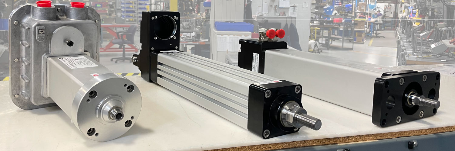
The Exlar Advantage
Understanding the Difference
Electric Actuator Choices for Linear Applications
So what are the alternative choices available to engineers?
1. Linear Motors
To picture a linear motor, cut open a traditional brushless servo motor. Lay the magnets and armature flat and then curl the rotor back into a tube in the other direction. This leaves the magnet poles arranged parallel to the actuator's output rod instead of radially around the rotor.
The stator looks like a typical stator from the outside but on the inside the phases are aligned to commutate along the length of the motor instead of around the circumference. Force is produced through the interaction of the windings with the permanent magnets attached to the motor's movable output rod. Since there is no opportunity in this design to multiply the magnetic force by mechanical means (by gear reducer or lead screw) the amount of force produced is strictly limited by the strength of the magnetic fields and the amount of magnets employed.
The one major attribute of a linear motor is the ability to produce very high acceleration and speed. However, this comes at the expense of low continuous force capability and excessive heat generation and thus lower efficiency. In most applications where a fluid power actuator is to be replaced, the application involves high force at low speed; and frequently the actuator must stop and hold a force. It is in this instance that linear motors are at their very worst.

2. Acme Screws
An Acme thread is a common lead screw thread profile that offers high capacity and simple manufacturing. It is typically found where large loads are required, but speed and duty cycle are minimal. Acme screws have sliding friction surfaces and are limited to a maximum 60% duty cycle.
The friction in the Acme screw causes rapid heating, and continuous operation is likely to result in a screw failure. Acme threads are low efficiency due to the design incorporating sliding friction and the thread angle. The low efficiency limits the operating rpm and duty cycle significantly compared to roller screws or ball screws.
3. Ball Screws
A ball screw's mechanical limitations render it best suited for applications where only moderate performance is required. The balls being discharged from the end of the race need to turn to the beginning of the race as the balls translate down the two load bearing surfaces. A sharp turn in the tube exists at both ends and the resistance of movement at these end-turns impedes the balls' movement. These balls, not being constrained in the return tube start colliding with each other. The vibration energy levels grow at an exponential rate as the rotational velocity increases which decreases efficiency and generates the loud noise associated with ball screws.
4. Roller Screws
This compact device, developed in the 1950’s is a complex interplay of mating surfaces which results in longer travel life, higher rotational speeds, greater efficiency at high speeds, and quiet operation. To achieve the promise of long life, all force transmission surfaces need to make contact uniformly while under load. This requires extreme precision in the manufacture of the load bearing mating components and the timing gears necessary to guarantee the true roll of the rollers.

